In the first part of this series, we defined the materials, cutting scenarios, and selected the necessary tools for our milling operations. Now, in this second article, we will shift our focus to calculating the spindle power required to execute these operations efficiently. We will dive into the detailed analysis of spindle power usage, considering varying ADOC and RDOC values and exploring how different cutting conditions impact performance. Additionally, we will explore spindle utilization and how it affects the overall system load. By combining these calculations and insights, we will conclude with a well-informed decision on the optimal spindle size that ensures both efficiency and precision for our CNC project. This analysis will provide the final piece of the puzzle, allowing us to confidently move forward with the build.
Reviewing End Mill Documentations
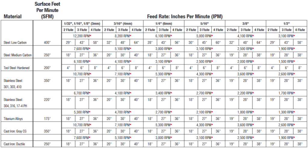
Now that we have selected the appropriate end mills for each material—wood, aluminum, and steel—we can turn to the manufacturer-provided dataset to assess what critical information is available and what we may need to calculate ourselves. The dataset offers key variables such as maximum RPM, feed rates (IPM), and chip load per tooth, which will be directly used in our spindle power calculations. By reviewing what is provided, we can identify areas where additional calculations are necessary, such as determining cutting forces or spindle torque, allowing us to fill in the gaps and create a comprehensive picture of the spindle’s power requirements for each milling operation.
Had these values not been provided, we would have drawn upon the knowledge covered in previous articles, where we extensively discussed cutting speeds, feed rates, and chip loads. While any values we calculated ourselves would have been theoretical rather than experimental, they would still serve as a valuable starting point. This foundational understanding would help guide us in approximating the necessary parameters for spindle power sizing, even in the absence of manufacturer data.
Let’s begin by looking at the dataset provided for pine and black walnut. The Amana dataset provides a feed rate of 230 IPM with a chip load per tooth of 0.0064″ for a 3/8″ diameter down-cut bit, which also has a maximum RPM of 18,000 (Indicated in the Comprehensive Data Sheet). I am aware, however, that black walnut—being a much harder wood than pine—requires more force during cutting, meaning a slightly lower feed rate is more appropriate. Therefore, I will use the 230″ IPM as provided in the dataset for black walnut, which I deem suitable for spindle sizing calculations. For pine, a softer wood, I will adjust the feed rate to 260″ IPM, as accepted in the earlier aluminum end mill dataset.

Although I’ve increased the feed rate for pine, I don’t need to recalculate the chip load. The chip load per tooth provided in this dataset is reflective of the 230 IPM feed rate, but the final value needed for spindle power calculations comes from the feed rate itself, rather than the chip load. The chip load was a means to determine the appropriate feed rate, but now that I’ve established my feed rates, I can focus on those values directly to calculate spindle power. These values will guide our calculations, offering a more tailored analysis for both pine and black walnut in the context of spindle sizing.
Moving on to aluminum 6061, the recommended feed rate is between 110-180 IPM with a chip load per tooth of 0.003″-0.005″, using a 3/8″ diameter up-cut end mill. This end mill is optimized for high-speed cutting in aluminum, balancing quick material removal with proper heat dissipation to prevent excessive heat buildup. The tool’s maximum RPM is 18,000, ensuring that the spindle can operate at the high speeds necessary for efficient aluminum cutting. These values set a strong foundation for calculating spindle power in this scenario, as they outline how the end mill should perform under optimal conditions.
However, to avoid the extremes of slow feed or fast feed, which could introduce variations in performance and accuracy, we will choose to work with the average of both the feed rate range and chip load per tooth. The average feed rate becomes 145 IPM, and the average chip load per tooth comes to 0.004 inches. This approach allows us to mitigate the effects of slow feeds, which can increase tool wear and create excess heat, or fast feeds, which can overload the spindle and reduce cutting precision. By sticking to an average, we ensure a balanced performance, aligning well with the power estimation required for our spindle sizing.

Notably, the dataset also includes sections for both softwood and hardwood, indicating that the selected aluminum end mill could also be used to mill wood. However, we had previously determined that an up-cut design is less suitable for wood, especially when minimizing tear-out is a priority. To preserve surface quality, particularly for wood types like pine and walnut, we opted for a dedicated down-cut end mill for wood milling operations. Therefore, despite this aluminum end mill’s versatility, we selected tools better suited for each material, ensuring consistent and accurate tests for our spindle power calculations.
For stainless steel 316, the dataset indicates a feed rate of 38 IPM and a maximum RPM of 2,200 for a 3/8″ diameter tool with 4 flutes. These values reflect the significantly higher force required to machine such a hard material, compared to aluminum or wood. Although milling steel will never be part of this CNC build, this data provides a comparative understanding of the spindle power that would be required to cut stainless steel. This comparison helps in evaluating how the spindle might perform under the most demanding conditions, offering useful insights into its capacity even though the spindle will be primarily used for softer materials.
Critical Parameters & Calculations
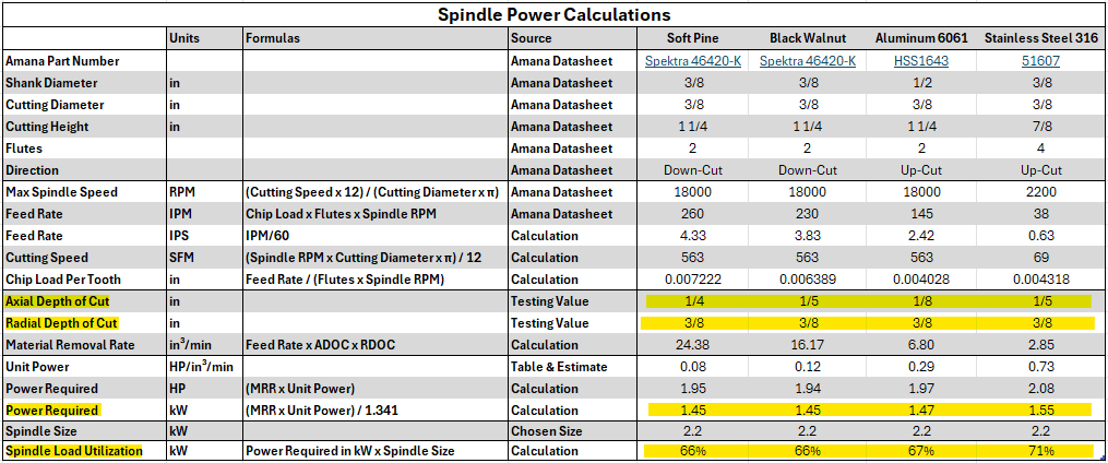
To properly calculate the spindle power required for our CNC setup, I gathered all relevant information from the datasheets of the selected end mills and documented key parameters. The table below outlines this compiled data, along with the step-by-step calculations that were conducted to arrive at the necessary power requirement. Each parameter, from chip load to material removal rate (MRR), plays a critical role in ensuring that the spindle size is sufficient to handle the cutting operations for different materials. Now, let’s discuss the table.
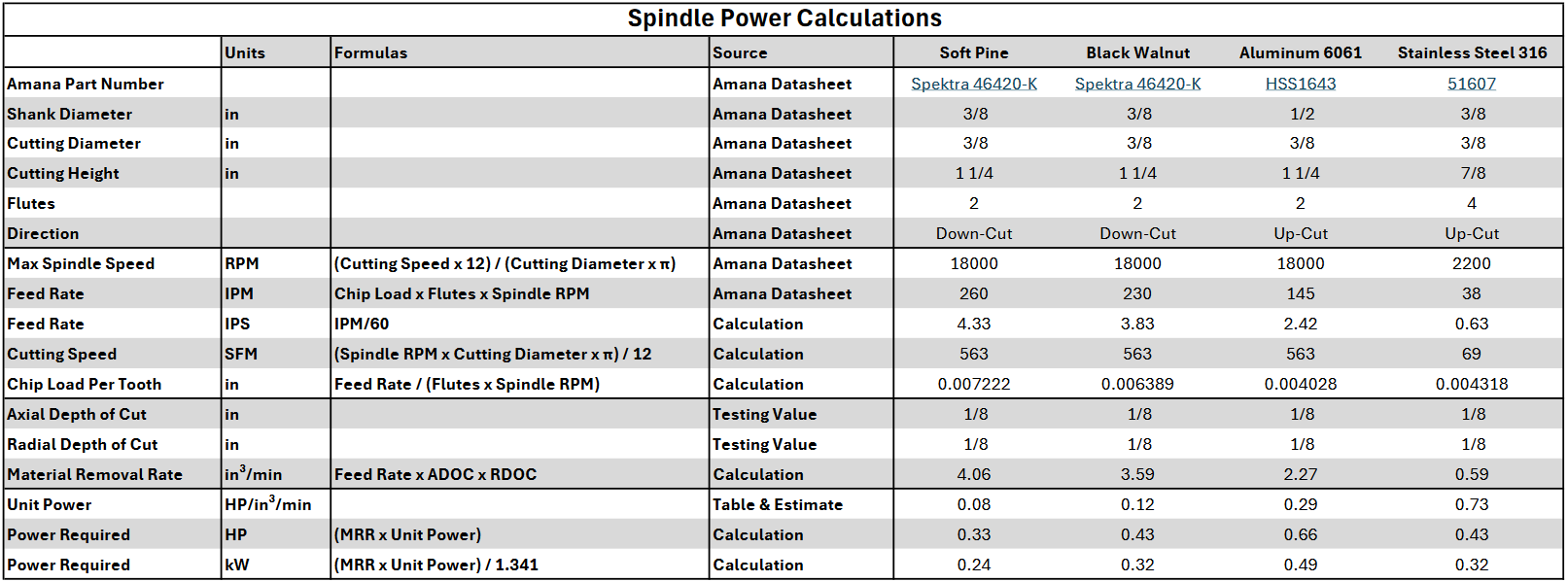
The “Max Spindle Speed” was selected directly from the Amana end mill datasheets, as they provide recommended maximum RPMs for each tool, tailored to ensure optimal performance while minimizing wear on the tool and the machine. The “Feed Rate” was also taken from the datasheets and adjusted accordingly for each material. These values represent the speed at which the tool moves through the material and were crucial in determining the material removal rate (MRR) and the spindle power required.
Additionally, I calculated “Feed Rate” in inches per second (IPS) to offer a more relatable reference, as it’s easier to visualize speeds over one second rather than over a minute. This helps in understanding how fast the tool would move through the material.
The “Chip Load per Tooth” was calculated using the formula derived from the previous articles, which factors in the feed rate, number of flutes, and spindle RPM. This value is essential for determining the efficiency of material removal, as it indicates how much material is removed with each cutting edge pass. The “Axial Depth of Cut (ADOC)” and “Radial Depth of Cut (RDOC)” were set at an initial testing value of 1/8″ for this scenario. However, these values were further tested as seen below with a range of values to fully understand how they affect the power required.
Next, we calculated the “Material Removal Rate (MRR)”, which is a key metric in determining how much material is removed during each pass of the tool. MRR is calculated by multiplying the feed rate by the ADOC and RDOC. This value helps us estimate the power requirements as it directly influences how much effort the spindle must exert to cut through material.
The “Unit Power” for aluminum and steel was referenced from a table in a prior article that defines typical power constants for various materials. For soft pine and black walnut, the unit power was estimated based on my understanding of the material properties and their relative hardness and resistance during the cutting process, as it could not be found anywhere online or in any book.
Lastly, the “Power Required” calculations for both horsepower (HP) and kilowatts (kW) were straightforward, following the formulas provided below, where MRR is multiplied by the unit power and converted into kW for easier reference and comparison across materials. These values are essential to evaluate the necessary spindle power for each material under specific cutting conditions.
By documenting the relevant data and performing calculations across various ADOC and RDOC values, we gain a clear understanding of the power requirements for each material with its respective end mill. This approach ensures that the spindle selection process is guided by precise, data-driven insights, leading to the most accurate decision possible.
Final Results
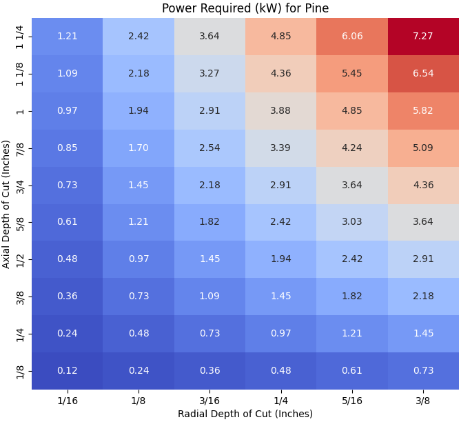
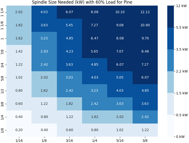
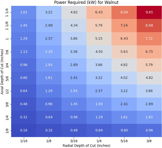
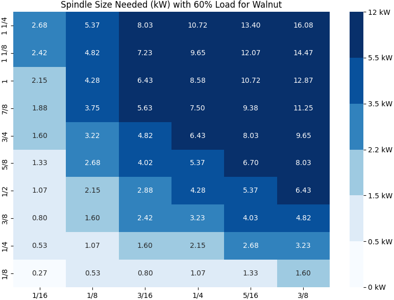
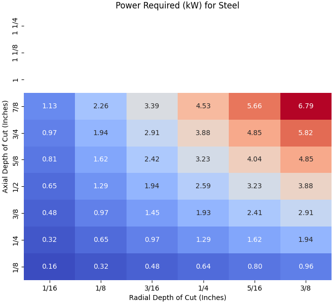
In the final analysis of spindle power, our primary goal was to assess the power requirements for spindles ranging between 1.5 kW, 2.2 kW, and 3.5 kW. These spindle sizes were deemed the most appropriate for our CNC build, considering the expected material and operation types. The charts produced in this analysis show the power needed for Pine, Walnut, Aluminum 6061, and Stainless Steel 316, under various combinations of Axial Depth of Cut (ADOC) and Radial Depth of Cut (RDOC).
The left-hand charts illustrate the power required for each material when pushing the limits of both ADOC and RDOC. This provides insight into the most extreme roughing operations possible with a 3/8″ end mill, which is useful for understanding the spindle’s upper limits. By examining these values, we can see how much power the spindle would need to perform such aggressive operations.
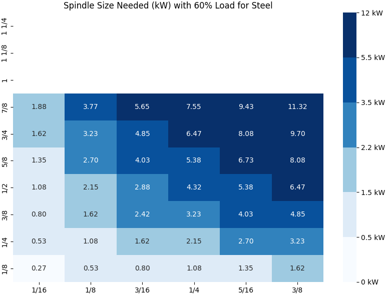
Meanwhile, the right-hand charts represent the spindle size needed if the values from the left were to correspond to 60% spindle load utilization during continuous operation. This helps in identifying what spindle size would be necessary to avoid overloading the spindle for the same cutting depths and feed rates. These charts are more reflective of real-world operational targets, allowing us to plan for efficient spindle use without pushing the motor too close to its limits.
In these heatmaps, I intentionally used the full cutting diameter and height of the end mill for a thorough analysis. However, in practical scenarios, it’s highly unlikely that these extreme conditions would be utilized consistently. While using the full RDOC is still common, employing the full ADOC is extremely rare. Typically, the maximum ADOC recommended is no more than three times the RDOC. In this study, that would be an ADOC of around 1-1/8 inches, but even for that, the feed rate would need to be slowed down by a factor of three to maintain cutting quality.
The takeaway here is that a higher RDOC is more valuable to examine than a higher ADOC in practical cutting scenarios. Focusing on optimizing RDOC, while keeping ADOC in check, ensures better spindle performance and cutting efficiency without overloading the machine.
A critical factor to consider is that these spindle power values are based on the specific feed rates for each material. As shown in the Spindle Power Calculations table, materials like Soft Pine and Black Walnut have significantly higher feed rates compared to harder materials like Aluminum 6061 and Stainless Steel 316. For instance, Soft Pine operates at a feed rate of 260 IPM, while Steel 316 has a much lower rate of 38 IPM. These discrepancies in feed rates directly influence the power required by the spindle.
However, if all materials were processed with the same feed rate, the power required to cut harder materials such as steel would rise dramatically. For example, if we ran Steel 316 at the same feed rate as Soft Pine or Black Walnut, the spindle power demand would be considerably higher. This highlights the importance of adjusting the feed rate based on material hardness to optimize spindle power consumption.
Pine & Black Walnut
Pine generally requires lower spindle power, with a maximum of 7.27 kW for the most aggressive cuts (high ADOC and RDOC). However, as discussed, real-world cutting operations wouldn’t reach such extremes. More realistic roughing cuts, focusing on a higher RDOC with a more moderate ADOC, show that spindle power requirements fall comfortably within the 2.2 kW range. For light to moderate cuts, even a 1.5 kW spindle could manage well, but for larger cuts, a 2.2 kW spindle would be ideal.
Walnut, being a bit denser than pine, pushes spindle power requirements higher. The charts show a maximum power need of 9.65 kW under extreme roughing conditions. But again, focusing on higher RDOC and a more moderate ADOC reveals that spindle power needs typically remain under 3.5 kW. This confirms that a 3.5 kW spindle would comfortably handle the toughest walnut cuts, while a 2.2 kW spindle could handle moderate operations.
Aluminum 6061
In analyzing the spindle power requirements for aluminum, a significant difference arises when comparing it to materials like wood. For example, the same 1/4″ ADOC and 3/8″ RDOC, which could be handled by a 2.2 kW to 3.5 kW spindle for wood, requires a 5.5 kW spindle when milling aluminum. This illustrates the higher power demands that aluminum places on the spindle, particularly when performing more aggressive cutting operations.
However, this also highlights the flexibility we have in spindle selection based on modifying the cutting parameters. By simply reducing the ADOC to 1/8″ while keeping the RDOC the same, the power requirement drops significantly. In this case, a 2.2 kW spindle could handle the operation with a little over 60% spindle load utilization, or alternatively, a 3.5 kW spindle could perform the task at below 50% utilization. This balance between adjusting cutting depths and selecting the spindle size can provide efficient operation while avoiding unnecessary spindle strain.

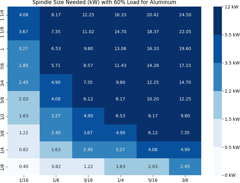
Thus, while a 5.5 kW spindle might seem necessary for the most aggressive cuts in aluminum, careful adjustments to ADOC and RDOC allow a more manageable spindle size, such as 2.2 kW or 3.5 kW, to be used without compromising the performance or longevity of the spindle. This approach is especially beneficial for CNC operations where versatility across materials is important, allowing the machine to handle both heavy and lighter tasks effectively.
Stainless Steel 316
Steel, particularly stainless steel, is a very demanding material. The power required for the heaviest cuts maxed out at 6.79 kW, but again, these represent extreme cases. When focusing on a higher RDOC and more manageable ADOC, spindle power remains under 3.5 kW in most cases. Still, steel benefits from a slower feed rate, so if spindle power requirements are a concern, it’s crucial to consider reducing feed rates to ensure the 3.5 kW spindle can handle the task without excessive strain. For moderate steel cutting, a 2.2 kW spindle may suffice, but a 3.5 kW spindle would offer more flexibility and longevity.
The Most Ideal Spindle Size For My CNC Build
In conclusion, while we explored spindle sizes up to 3.5 kW, this analysis has demonstrated the importance of adjusting ADOC and RDOC in real-world scenarios. High RDOC values can still be managed effectively with smaller spindles when paired with reduced ADOC, avoiding the need for excessive spindle power. The findings also emphasize that spindle power is not solely dependent on material hardness but is critically influenced by feed rates, making it essential to adjust cutting parameters appropriately for each material and operation type.
After careful consideration of all factors, including the relationship between machining time and material removal rate (MRR) discussed in a previous article, we have determined that a 2.2 kW spindle is the optimal choice for this CNC build. While a 1.5 kW spindle could serve as a minimum viable option for certain tasks, it would not provide the level of flexibility or efficiency required for a wide range of operations. In contrast, the 2.2 kW spindle strikes the ideal balance between performance and cost, making it the most practical choice, especially given that ER20 collets, which are necessary for my work, are generally available only with 2.2 kW spindles or higher.
As demonstrated in this article, larger spindles certainly offer more power, but they also introduce challenges such as increased forces on the machine and materials, which could lead to potential issues if not managed carefully. While a larger spindle may be preferable for more demanding tasks, the 2.2 kW spindle is more than sufficient for the majority of operations, particularly when adjusting Axial Depth of Cut (ADOC) and Radial Depth of Cut (RDOC) to optimize efficiency.
We’ve also shown that even a smaller spindle, like 500W, could technically cut through materials like aluminum with a reduced ADOC and RDOC, but this would be far from ideal and inefficient in practice. Therefore, the 2.2 kW spindle, operating at around 60% power load for most tasks where RDOC is above 80% and ADOC is under 20%, represents the best option. This provides the flexibility to handle a wide range of materials and cutting scenarios without being overpowered or underutilized.
wow