In earlier discussions, we explored the key components that define a CNC machine’s performance and precision, covering everything from structural materials to linear guide systems and motion drives. We then examined the intricacies of spindle power, collets, and cutting strategies, followed by a deep dive into speed and rates, which are critical for shaping our project scope. With these foundations in place, it’s time to translate those insights into clear project requirements.
Based on the types of projects I intend to pursue, I’ve identified specific features and capabilities that are crucial for achieving the desired performance and reliability. These project requirements balance practicality, cost-effectiveness, and the lessons learned throughout the design process. Let’s break down the essential project requirements that will guide the success of my CNC build.
Structural Requirements
Frame Material: Aluminum 6061 T6
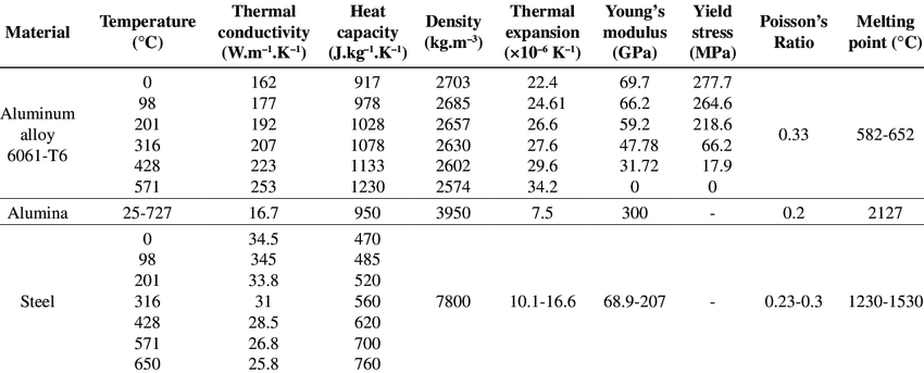
Aluminum 6061 T6511 is a well-balanced material for CNC frame construction, offering a combination of strength, rigidity, and workability. This particular grade of aluminum is known for its excellent mechanical properties and good resistance to corrosion, which is crucial for maintaining the structural integrity of the CNC machine over time. By choosing Aluminum 6061 T6511, I ensure that the machine remains lightweight enough for easier assembly and transportation while still providing the necessary rigidity to prevent deflection during machining, especially when working with harder materials like aluminum and hardwood. The attached chart provides a detailed comparison of the material properties of Aluminum 6061-T6, alumina, and steel, highlighting why Aluminum 6061 is an optimal choice for this application.

Frame Profile: Aluminum Bars & Plates
Opting for aluminum bars and plates instead of extrusions allows for greater flexibility in the design and construction of the CNC frame. Aluminum extrusions, while popular for their ease of use and modularity, may not offer the same level of rigidity as solid bars and plates, especially in a machine that demands high precision. Using solid aluminum bars and plates gives the frame additional mass and stability, reducing the chances of vibration and deflection. This choice also allows for more customizability in the design, enabling me to reinforce specific areas of the frame where more rigidity is required.
Frame Fixture: Tapping
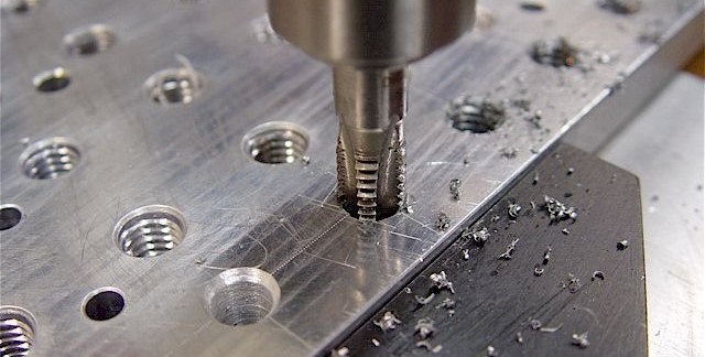
For the frame fixture, I’ve chosen to use tapped aluminum with steel screws due to the reliability and control this method offers during assembly. This approach involves manually drilling over 150 screw holes, counterboring many, and then tapping threads into the aluminum. While this process is labor-intensive and time-consuming, it allows for precise control over the assembly, ensuring each component is securely fastened and aligned correctly. This precision is essential for maintaining the structural integrity and accuracy of the CNC machine. The image below illustrates the tapping process that will be undertaken to achieve this.

The screws, made of steel, provide the necessary strength to hold the aluminum frame components together under the stresses of machining. However, using steel screws in aluminum poses a potential risk of galvanic corrosion, where the aluminum may corrode faster in the presence of steel, especially if exposed to moisture. Although this issue is not an immediate concern, it is something I will monitor closely and consider addressing as I continue refining the CNC design.
Another critical consideration is the vibration generated by the motors and spindle during operation, which could cause the screws to loosen over time. This loosening could lead to misalignment of components or even serious damage to the machine. To prevent this, I plan to use thread-locking solutions like ‘Loctite’ on the screws, ensuring they remain securely in place despite the vibrations. This measure will help maintain the stability of the frame and the precision of the machine over its operational life.
Motion Requirements
Linear Guide System: Profiled Rails
I’ve chosen to go with profiled rail guides, or linear rails, as the preferred linear guide system for my CNC machine due to their unmatched precision and rigidity. Linear rails are known for their rigidity and smooth, low-friction movement, which ensures the accuracy I need for machining both wood and aluminum. The ball-bearing blocks allow for highly precise motion, minimizing wear over time and maintaining the tight tolerances crucial for high-quality results.
To fully harness the benefits of linear rails, I’m willing to dedicate the necessary time to perfectly align the rails during installation. Proper alignment is key to achieving the long-term accuracy and performance that this system offers. I believe the investment in both effort and materials will pay off, ensuring the CNC machine delivers the reliability and precision essential for the types of projects I plan to undertake.
Motion Drive System: Ball Screws
For my CNC build, the choice to go with ball screws as the motion drive system was an easy decision. Ball screws offer simplicity, high efficiency, and the precision I need for both wood and aluminum projects. Their low friction, reduced wear, and minimal backlash make them an ideal option for maintaining accuracy over time, and the overall cost is quite affordable given the performance they deliver. This system promises the precision I need without compromising on ease of use or efficiency.
Rack and pinion was the second-best option I considered, but it ultimately felt too complicated for my build. The potential need for a gearbox, combined with the added complexity of alignment and maintenance, didn’t seem worth it. Since I don’t plan to build a machine large enough for ball screws to become prohibitively expensive or unavailable, sticking with ball screws makes the most sense for ensuring optimal performance without unnecessary complications.
Size Requirements
Maximum Machine Size: 1200mm x 1000mm
The decision to limit the machine size to a maximum of 1200mm x 1000mm is primarily based on the space available in my garage. This size strikes a balance between providing a generous work area and ensuring that the CNC remains compact enough to fit comfortably within my workshop. Additionally, one of the key factors influencing this decision was the significant increase in costs that accompanies larger machine sizes. As the size of the machine increases, so do the material and component costs, making it crucial to find a practical limit that meets my needs without breaking the budget.
Choosing a round number of 1 meter in length felt like a good, practical decision for my use case. It offers more than enough space for the types of projects I envision, including the original inspiration for this CNC build—creating custom inlay chopping boards. In fact, this size is far more than what I need for those projects, indicating that I have already considered future needs and growth potential in my decision. By opting for this machine size, I ensure that the CNC is capable of handling a wide range of tasks while remaining within a manageable and cost-effective range.
Minimum Work Area: 1000mm x 750mm
The work area of 1000mm x 750mm is an estimated minimum based on my current understanding of what can be achieved within the maximum machine size of 1200mm x 1000mm. This estimation is designed to provide sufficient space for a variety of projects, from small, intricate parts to larger components, ensuring versatility in the types of tasks the machine can handle. However, this work area is not set in stone and will likely be adjusted as the final design is developed and refined.
Spindle Requirements
2.2kW Power (Tentative)
I have tentatively selected a spindle power of 2.2kW because it offers a good balance between power and manageability for my intended applications. This level of power is generally sufficient for machining both aluminum and hardwood, providing enough torque at lower RPMs for aluminum and the necessary speed for hardwood. While I have yet to perform the precise calculations to verify this choice—calculations that will be based on cutting speed and spindle RPM—2.2kW is widely accepted in the industry as an appropriate choice for CNC machines of this caliber.
It is possible that I may decide to change my mind later, based on more detailed calculations or if I find that I have underestimated my future requirements. In such a case, I might consider upgrading to a 3.5kW spindle. However, this is not a decision I would take lightly, as a more powerful spindle would generate significantly higher forces in terms of vibration and torque. These increased forces would likely necessitate a more rigid and stiff frame to maintain the machine’s precision and stability, which could lead to additional complexities and costs in the design and construction of the CNC.
Suitable RPM Range
The spindle must be capable of operating at RPMs suitable for both aluminum and hardwood, as these are the primary materials I intend to work with. For aluminum, lower RPMs are typically required to avoid overheating and achieve a good surface finish, while hardwood machining benefits from higher RPMs for faster material removal and smoother cuts. By selecting a spindle with a wide RPM range, I ensure the machine’s versatility across different materials, enabling it to handle a variety of projects without compromising on performance.
Ceramic Bearings
For my CNC machine build, I have decided to opt for a spindle equipped with ceramic bearings. Ceramic bearings offer several advantages that align well with my project’s needs, particularly in terms of precision, durability, and high-speed operation. Ceramic bearings have lower friction and generate less heat compared to traditional steel bearings, which allows the spindle to maintain better performance over extended periods of use. This is especially important for my intended tasks, which involve machining aluminum and other materials that require higher RPMs and sustained precision.
Additionally, ceramic bearings provide excellent wear resistance and longevity, ensuring that the spindle remains reliable even under heavy workloads. While they are more expensive upfront, the long-term benefits of reduced maintenance and enhanced performance make ceramic bearings the ideal choice for my machine.
Water Cooled System
I have chosen a water-cooled spindle because I believe it will outlast, outperform, and handle longer durations of operation or more intense jobs with minimal damage to itself. Water cooling is significantly more effective than air cooling at dissipating the heat generated during prolonged machining sessions, especially when working with materials like aluminum, which can produce substantial heat. By maintaining consistent spindle temperatures, a water-cooled spindle reduces the risk of overheating, thereby extending its lifespan and ensuring it remains reliable over time.
A common issue that arises in spindles over time is the deterioration of bearings due to excessive heat and thermal stress. An important advantage of water-cooled spindles is their positive impact on bearing life. The consistent and lower operating temperatures provided by water cooling help reduce thermal stress on the spindle’s internal components, including the bearings. This contributes to a longer lifespan for the bearings, as they are less likely to experience the accelerated wear that can occur in air-cooled spindles due to higher and fluctuating temperatures.
With these benefits, a water-cooled spindle is better equipped to perform demanding tasks without sacrificing performance or enduring excessive wear and tear, making it an optimal choice for a wide range of machining projects.
Power Requirements
Before diving into the specific power requirements for my spindle and axis motors, I want to note that I plan to publish a series of articles dedicated entirely to the topic of power. In those articles, I’ll explore in greater depth the electrical needs of a CNC machine, from spindle power setups to the role of different types of motors. However, for now, there are several other critical topics that take precedence and need to be addressed before we can fully dive into the intricacies of power management.
Spindle: Split Phase / 240V / 60Hz / U.S. Outlet
The primary reason for choosing a split-phase, 240V spindle is that I already have a 240V outlet installed in my garage for my welder. This outlet is on a separate circuit with a higher amperage fuse, allowing me to run the spindle confidently without worrying about tripping the circuit due to peaks in current usage. Having this dedicated circuit provides a stable and reliable power supply for the spindle while ensuring that the rest of the CNC system operates independently without being affected by the spindle’s power demands.
This setup is especially beneficial because it allows the spindle to be powered separately from the rest of the CNC system, reducing the risk of electrical interference and providing an additional layer of safety. Split-phase power also offers sufficient torque and efficiency for my spindle, making it well-suited for demanding machining tasks, particularly when working with materials like aluminum and hardwood. The stable and efficient power delivery ensures smoother operation with less vibration, which is critical for maintaining precision.
Axis Motors: 1 Phase / 120V /60 Hz / U.S. Outlet
I aim to power the axis motors by a 1-phase, 120V setup, which is typical for smaller CNC machines and home workshop environments. This choice ensures compatibility with standard North American outlets, making the machine more accessible and easier to set up without requiring specialized electrical work. The 120V supply is sufficient to power the stepper motors or servo motors that will drive the CNC’s axes, providing reliable movement control while keeping energy consumption at a manageable level.
Additional Requirements
Accuracy: 0.1mm/m
An accuracy of 0.1mm per 1m of travel is targeted to ensure that the machine can produce parts with a high level of precision. In any machine, the overall accuracy is only as good as the least accurate component. In the case of a CNC machine, where multiple parts are functioning together simultaneously, inaccuracies can accumulate quickly. This makes it essential to consider every component, from the rigidity of the frame to the precision of the motion system and the quality of the spindle and cutting tools, to achieve the desired level of accuracy.
While this accuracy target may not be up to the standards required by high-end industrial machines—such as those used in aerospace manufacturing or for producing highly precise components for other machinery—it is more than sufficient for the types of projects I anticipate working on. For the parts I can foresee myself manufacturing, this level of precision will meet or exceed the requirements, whether for functional or aesthetic purposes. This targeted accuracy strikes a balance between achieving high precision and maintaining a practical, cost-effective approach suitable for my CNC build.
Cost: Under $5,000 CAD
Keeping the total cost under $5000 CAD is a critical requirement for this project. While this budget may seem high for the average DIY inventor, it is still quite moderate when compared to the market price of CNC machines with similar performance and capabilities. This budget constraint ensures that the project remains accessible and affordable without sacrificing quality or functionality.
Optional Features (To be planned)
T-Slot Baseboard: Future Upgrade (No. 1)
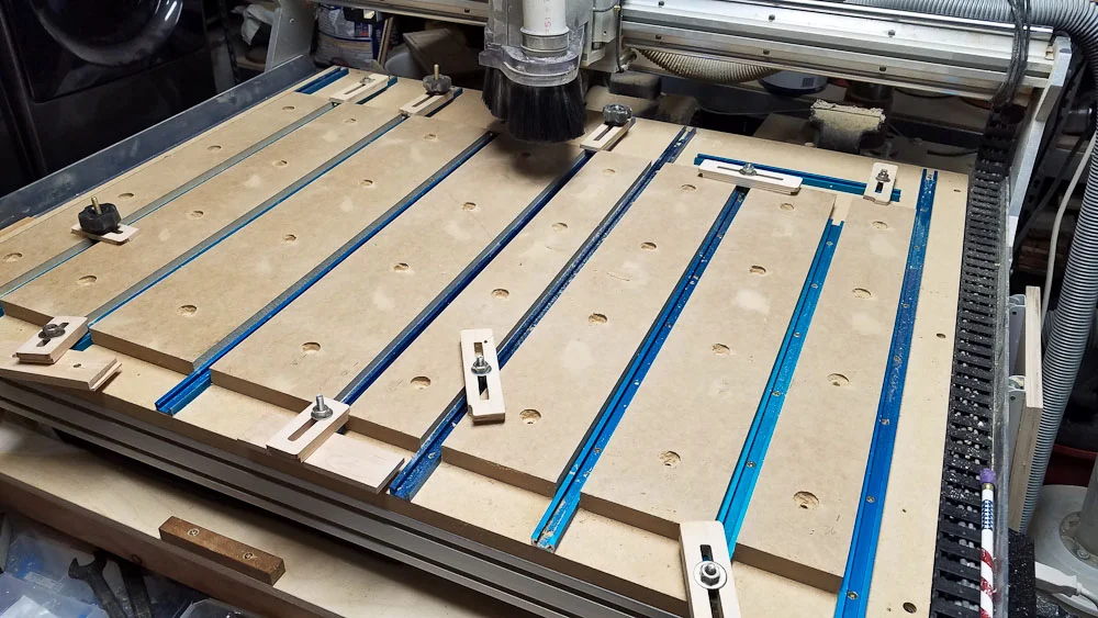
As part of the final design, I aim to implement a T-slot baseboard combined with a 1″ thick MDF board. This feature is integral to the functionality of the CNC machine, providing a versatile and customizable work surface. The T-slot design allows for flexible fixturing, enabling easy clamping and securing of various work pieces during machining. This is particularly beneficial when working with intricate or irregularly shaped projects, as it offers the flexibility needed to position and hold materials securely.
The 1″ thick MDF board will serve as a sturdy, flat surface that complements the T-slot base, and it can be easily replaced if it becomes damaged over time. This combination enhances the overall efficiency and adaptability of the machine, ensuring that it can handle a wide range of tasks with precision and ease.

Vacuum System: Future Upgrade (No. 2)
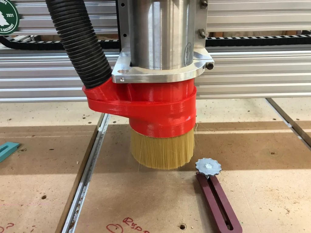
After countless woodworking projects, I’ve come to appreciate the importance of a good vacuum system in the shop. Tools like table saws and planers can quickly create massive amounts of dust and wood shavings, which not only clutter the workspace but can also hinder the quality and accuracy of cuts. If these basic woodworking tools cause so many issues without a vacuum, I can only imagine the challenges a CNC machine—designed for precision down to the millimeter—would face without proper dust management. That’s why a vacuum system is a necessary upgrade – it will enhance the cleanliness and safety of my workspace and significantly improve the quality of my woodworking pieces.

Cooling & Lubrication System: Future Upgrade (No. 3)
While not included in the initial build, a cooling and lubrication system is highly considered for future upgrade. This system would enhance the machine’s ability to handle longer, more demanding machining sessions, particularly when working with metals. It will allow me to make cuts in the metal without fear of welding due to heat, or breakage of bit due to stress imposed upon it. By planning for this upgrade, I ensure that the machine can evolve with my needs, adding capabilities as required without needing a complete redesign.
Sound Dampening Enclosure: Future Upgrade (No. 4)
To reduce noise levels and create a more comfortable working environment, a sound dampening enclosure is considered for future implementation. This upgrade will involve adding materials or enclosures that absorb and reduce the noise generated by the machine, making it more suitable for use in a home workshop setting. As with other upgrades, planning for this feature in the future allows the machine to adapt to changing needs and environments.
Automatic Tool Changing: NOT Considering for Future Upgrade
While an automatic tool changing system (ATC) can significantly improve productivity, it is not being considered for this build or future upgrades. The decision to exclude ATC is based on the additional cost and complexity it would introduce, which does not align with the budget and simplicity goals of the project. Instead, manual tool changes will be used, which, while slower, are more cost-effective and sufficient for the types of projects I plan to undertake.
Next Steps
By carefully defining these requirements, I have laid a solid foundation for the design and construction of a CNC machine that is both capable and cost-effective. Each decision, from the choice of frame material to the power requirements and potential future upgrades, is guided by a clear understanding of the machine’s intended use and the practical constraints of the project. As I move forward with the build, these specifications will ensure that the machine meets my current needs while remaining adaptable to future challenges.
In the next few articles, I will delve into the calculations that will guide the selection of critical components such as the spindle, motors, and gantry movement systems. These calculations, based on logical reasoning and detailed analysis, will help finalize the choices for each part, ensuring they align with the overall goals of the project. Once these components have been selected, the next phase of the journey will begin: the CAD design of the CNC machine. This step will bring together all the planning and calculations, translating them into a tangible, functional design ready for construction. Stay tuned as we continue to build this machine, piece by piece, with precision and purpose.