To introduce this article, it’s essential to set the stage for the role that power systems play in spindle selection for CNC machines. When setting up a CNC machine, choosing the right spindle is a crucial step, but understanding the power system your machine will rely on is equally important. Power systems, whether single-phase, split-phase, or three-phase, directly impact the performance, stability, and capacity of the spindle, and by extension, the entire CNC operation. Each system offers different advantages and limitations depending on your setup, environment, and machine requirements.
This article will guide you through the different types of power systems available—single-phase, split-phase, and three-phase—explaining how each works and how to select the right one for your CNC needs. Along with this, the article will explore spindle load utilization and its importance, including how it affects the lifespan and efficiency of your spindle. Understanding these key concepts will help you make informed decisions about selecting both the spindle and power system for your CNC machine, ensuring optimal performance and durability.
By the end of this article, you’ll not only be able to select the appropriate spindle power for your CNC setup, but you’ll also have a deeper understanding of spindle load management and how different power systems impact long-term machine performance.
Power Systems: A Prerequisite to Spindle Selection
In North America, CNC systems typically operate on either single-phase, split-phase, or three-phase power. Each of these systems provides a different level of power and performance, making it crucial to match your CNC machine’s electrical requirements with the appropriate power setup. This ensures not only reliable performance but also that you’re able to select the correct components—spindle, motors, power supplies—that align with your operational needs. Let’s explore the types of power systems available and how they apply to CNC machines.
Single-Phase Power: The Basics
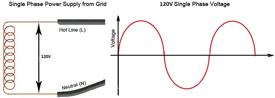
Single-phase power is the most common form of electrical supply in residential homes and small workshops, operating with a single alternating current (AC) voltage. In North America, this typically provides 120V, using two wires—one phase wire and one neutral wire. In this system, the AC voltage alternates between positive and negative values, following a sinusoidal waveform. This wave peaks at positive and negative voltages and crosses zero twice per cycle, meaning the power delivery fluctuates between these points. In countries like Canada, where the frequency is 60Hz, this fluctuation happens 60 times per second.
Split-Phase Power: The 240V Alternative
Most residential homes in North America, including Canada, are wired for split-phase power. While technically still a form of single-phase power, split-phase provides an important advantage: it delivers 240V instead of the 120V typically available in single-phase systems. Split-phase power is achieved by splitting the single-phase AC supply into two “legs” of 120V each, which are 180 degrees out of phase with each other. This allows for higher voltage to be delivered for more power-demanding appliances, such as dryers, ovens, and importantly, CNC systems. The result is a more powerful and efficient delivery of energy that addresses the shortcomings of standard single-phase power.

Three-Phase Power: The Industrial Standard
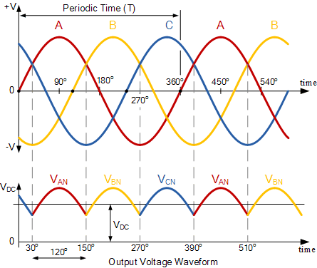
Three-phase power is the gold standard for industrial applications. Unlike single-phase and split-phase power, three-phase power uses three alternating currents, each 120 degrees out of phase with one another. This results in constant power delivery, with no zero-crossing points in the waveform. Three-phase power offers smoother, more efficient energy transmission, which reduces vibrations in motors and increases overall stability. These systems are more efficient because power is delivered continuously, allowing for higher torque, better efficiency, and the ability to handle larger, more demanding motors and loads.

Choosing the Right Power System For CNC
In selecting the power system for a CNC machine, understanding the benefits, opportunities, and limitations of single-phase, split-phase, and three-phase power is crucial. Each of these systems brings its own set of strengths and weaknesses, directly influencing the performance, stability, and capacity of the machine.
Advantages & Disadvantages
Single-phase power, the most common form of electricity available in residential homes, offers simplicity and accessibility. Its availability makes it an attractive option for hobbyists and small workshops. However, it operates on a basic waveform, fluctuating between positive and negative voltage with brief zero-crossings where no power is delivered. For CNC users working with spindles under 1.5 kW, this system performs adequately for light-duty tasks such as woodworking or engraving. However, when tackling harder materials like aluminum or taking on long-duration projects, single-phase power can reveal its limitations. The drop in power at zero-crossing points can cause torque fluctuations, reduce precision, and increase wear on cutting tools. While single-phase is sufficient for smaller, less power-intensive operations, its lack of stable, continuous power makes it less ideal for heavier workloads.
Split-phase power, commonly available in residential garages as 240V circuits, offers an important upgrade over standard single-phase systems. The increased voltage provides more power to drive CNC spindles, especially those up to 2.2 kW, allowing for higher torque and greater efficiency when working with tougher materials. The 240V system significantly reduces the inconsistencies seen in 120V single-phase power, providing more stable and reliable performance during prolonged use. This enhanced stability allows users to machine materials like aluminum and mild steel more effectively while reducing the risk of performance drops, overheating, or tool wear. For many CNC users operating from home, split-phase power represents a practical middle ground—offering greater performance without the need for industrial-level infrastructure. The main limitation is that even though split-phase offers better power delivery, it is still constrained by the availability of 240V and may not handle the needs of larger CNC systems.
Three-phase power, on the other hand, is the gold standard for industrial applications. This system provides continuous, balanced power with no zero-crossing points, making it the most efficient option for CNC machines running spindles above 3 kW. The ability to deliver consistent, uninterrupted power means that three-phase systems can handle large-scale operations and demanding materials, such as deep cuts in steel or large-scale aluminum machining. Furthermore, the smooth and stable power delivery reduces wear and tear on CNC components, improving longevity and minimizing maintenance. However, three-phase power is typically unavailable in residential settings, which limits its use to commercial or industrial environments.
Choosing Spindles with Split-Phase Power Capability
Because the CNC I am building will be operated out of my garage, I am limited to the split-phase power system available in most residential setups. However, this is still an excellent option for my needs. The 240V supply from split-phase power offers far more opportunities for spindle selection compared to the standard 110V system. With 240V, I can confidently run spindles up to 2.2 kW, which opens up the possibility of working with a wider variety of materials, including aluminum, without worrying about power drops or limitations. This ensures I can handle more demanding tasks while still operating within the confines of a residential power supply, making split-phase the ideal solution for my CNC build.
Spindle Load Utilization and Management
Spindle utilization is a key factor in ensuring the long-term efficiency and performance of any CNC machine. Essentially, it measures how much of the spindle’s available power is being used during machining operations. Operating too close to the spindle’s maximum power capacity can lead to several issues, including overheating, increased wear, and even potential failure of the spindle over time. On the other hand, underutilizing the spindle can result in inefficient operations, as you’re not leveraging the spindle’s full potential. Striking the right balance is crucial for achieving both longevity and high performance.
Understanding Spindle Utilization
Spindle utilization is expressed as a percentage of the spindle’s maximum power capacity. For example, if a 3.5 kW spindle is performing a task that requires 1.75 kW of power, the utilization rate would be 50%. Ideally, a CNC machine should operate within 50–70% spindle utilization for continuous operation, with peaks allowed for brief periods. This balance ensures that the spindle remains within its cooling capabilities, avoiding excess heat buildup and wear.
For roughing jobs or more demanding tasks, the goal is to operate between 60% and 80% spindle utilization. This provides enough headroom to accommodate sudden spikes in power demand, such as when cutting into tougher material or making deeper cuts. However, it’s important to note that short bursts of increased power can sometimes push the spindle utilization beyond 100%.
Peaks and Overload Risks
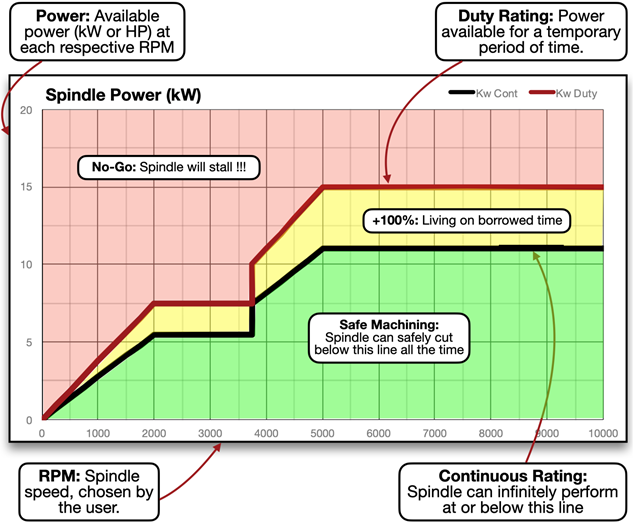
During operations, it’s common for power demands to spike above the spindle’s set utilization target, especially when cutting through tougher materials or making deeper cuts. For instance, even if the spindle is running at a target load of 60%, there can be temporary surges that push the spindle beyond 100% utilization. These brief spikes are generally manageable, but when sustained over long periods, they pose a risk. Operating above 100% means the spindle is generating more heat than the cooling system can handle, which can lead to overheating.
If the spindle runs too long at this overloaded state, critical components—such as the motor and bearings—begin to experience excessive wear, and in the worst-case scenario, the spindle may stall or fail altogether. In extreme cases, reaching 200% utilization is the limit before a spindle stalls, but sustained high utilization, even at levels above 100%, can drastically reduce the spindle’s lifespan. As a result, it’s crucial to avoid prolonged operation over 100% utilization to prevent damage.
Short-Term Load Surges and Commercial CNC Practices
Many spindle motors are designed with two ratings: a continuous power rating and a higher, short-term rating that can last 5 to 20 minutes. This higher rating allows the spindle to handle short bursts of heavy load without damage. For commercial CNC operations, where production speed is critical, spindles are often run close to or beyond their rated power capacity. In these cases, operators may choose to sacrifice some spindle life for faster machining cycles. As long as the peaks are within the short-term range and the spindle isn’t constantly overloaded, businesses can justify running spindles near their maximum utilization.
However, for non-commercial applications like ours, maximizing spindle throughout is not a priority. Our focus is on reliable, consistent performance without pushing the spindle to its limits. Therefore, we aim to keep our spindle utilization within 50–70% for continuous operations. Occasional spikes over 100% are acceptable, but sustained operation at these levels can lead to long-term damage and reduced tool life.
Spindle Load Charts & Instruments
Where to Find Spindle Load Charts
Spindle load charts can generally be found in the manufacturers technical specs or the spindle product manuals. Most reputable manufacturers, especially those that produce high-performance CNC spindles, include load charts in the technical documentation of their products. These charts outline the spindle’s power output at different RPMs and how efficiently it operates at various loads. Look for these documents on the manufacturer’s website or in product catalogues. However, if you’ve already purchased a spindle or are considering a specific model, the product manual will likely contain detailed charts and graphs that show how the spindle performs under different loads. These manuals also provide other critical specs, such as power consumption, torque, and cooling requirements.
Instruments and Devices for Monitoring Spindle Load
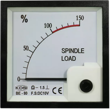
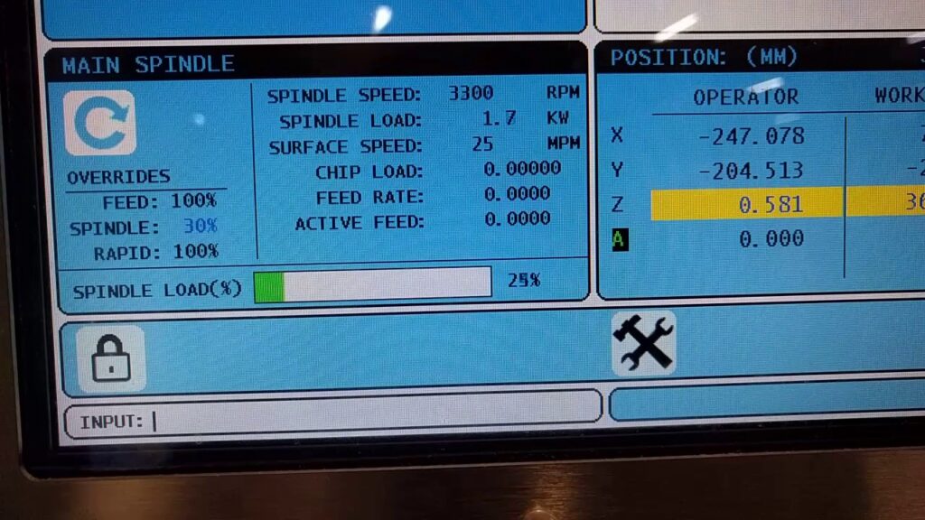
Once the spindle is selected and integrated into the CNC machine, it’s crucial to monitor its load during operation to ensure efficient and safe usage. The spindle load is typically monitored by the CNC machine’s control system or through external load meters. Below are the most common instruments for monitoring spindle load:
- CNC Machine Control System: Modern CNC machines are often equipped with built-in sensors that track spindle load in real-time. These control systems provide a display of spindle load as a percentage, allowing operators to see how close the spindle is operating to its maximum capacity. This system is crucial for adjusting feed rates, spindle speeds, and cutting depths to avoid overloading the spindle.
- Spindle Load Meters: Some machines may be equipped with spindle load meters, which display the spindle’s real-time power consumption. These meters are often used to help operators ensure that the spindle is running within its optimal utilization range. If load spikes are detected, adjustments can be made to the machining parameters.
- Machine Monitoring Software: Many industrial CNC systems offer monitoring software that not only tracks spindle load but also logs data over time. This software helps to analyze trends and identify overload patterns based on spindle’s operating history.
- PLC (Programmable Logic Controller): For more advanced setups, a PLC can be used to monitor spindle load. This device communicates with the CNC machine’s sensors to provide real-time data, which can be visualized or acted upon automatically by adjusting speeds or stopping the machine if it detects dangerous load levels.
Key Takeaways
- Spindle Load Utilization is Crucial: Managing spindle load ensures both efficiency and longevity. Operating at 50-70% of spindle capacity during continuous use strikes the right balance between performance and spindle life.
- Short-Term Surges Are Acceptable: Spindle power can exceed 100% for short periods during rough cuts, but sustained operation at or above this level risks overheating and component failure.
- Use Load Charts for Guidance: Spindle load charts, found in manufacturers’ specs, offer valuable insight into power consumption, efficiency, and potential overheating risks.
- Monitoring Devices Enhance Performance: Using built-in spindle meters, CNC control systems, or software ensures real-time tracking and management of spindle load to prevent overuse or failure.